Proportional Control Valve
What is a Proportional Control Valve?
A proportional control valve is a type of pneumatic valve that controls air flow rate proportionally to an electrical input signal — unlike a simple on/off valve, it can continuously adjust flow, pressure, or direction based on a varying current or voltage input. By precisely regulating the spool position via an electromagnetic coil (solenoid), it achieves smooth, fine-grained control of pneumatic actuators (cylinders or grippers), enabling variables such as cylinder velocity, output force, and motion trajectory to be modulated with high accuracy.
This project covers the complete product lifecycle: concept design, detailed CAD modeling, kinematic analysis, tolerance stack-up management, prototype testing, supply chain coordination, and production documentation — applying mechanical engineering fundamentals to a real-world industrial component.
Design Overview
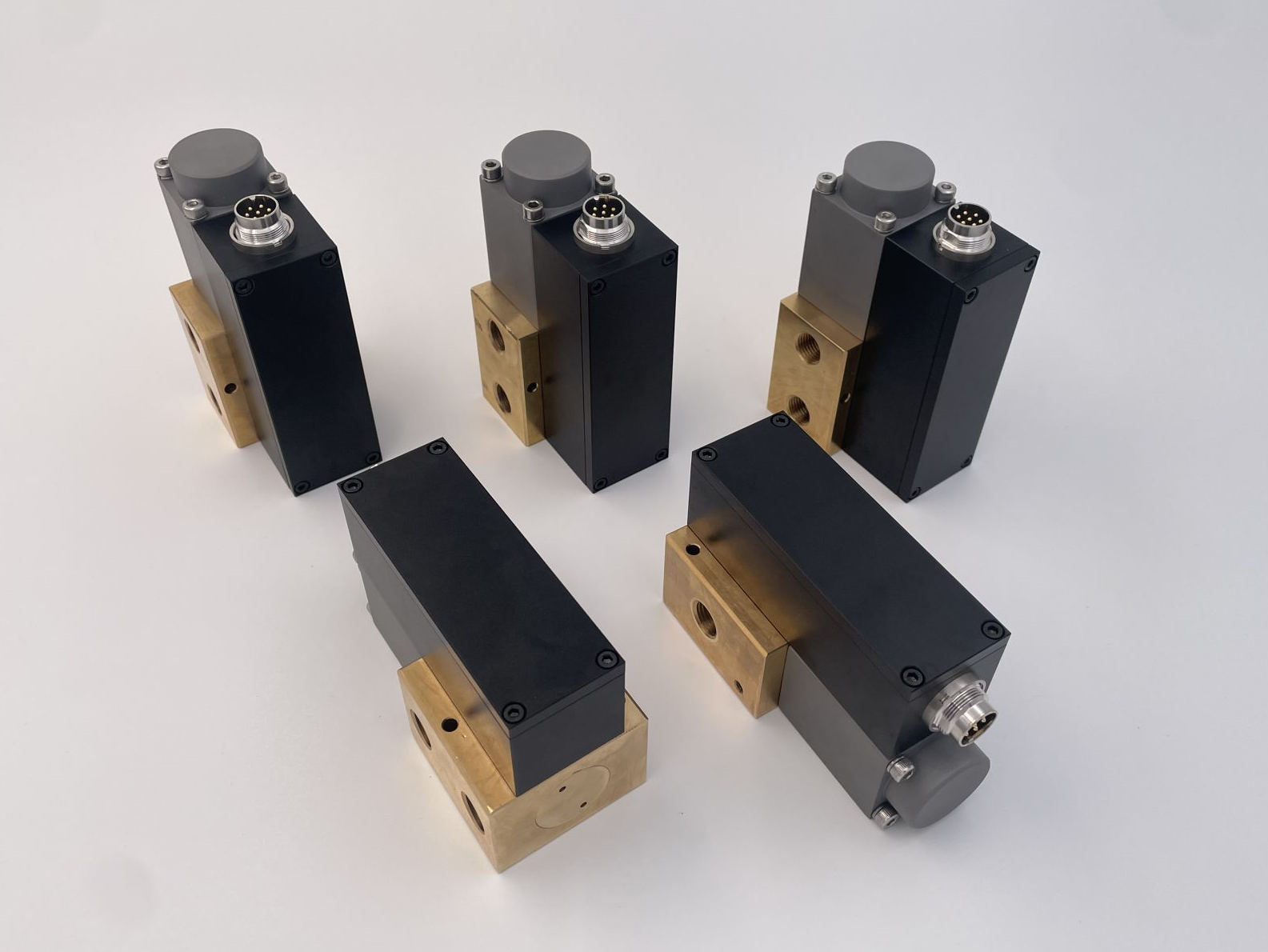
This assembled view highlights my ability to turn a valve concept into a complete product form, integrating the main body, brass base, electrical connector, and pneumatic ports into one manufacturable design.
📄 Valve Manual (PDF)Detailed CAD
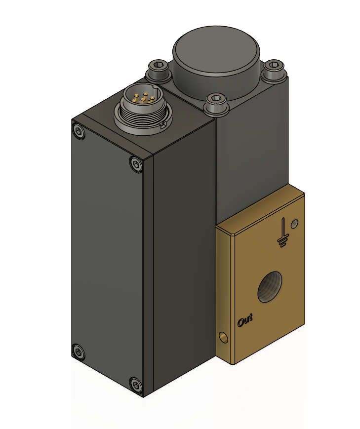
This 3D CAD model reflects detailed mechanical design work, with the housing, top cap, connector, brass base, and outlet features integrated into a coherent assembly.
Working Principle
This sectional animation demonstrates my understanding of the internal actuation path, showing how the central spool moves inside the housing during valve operation.
R&D Process Management
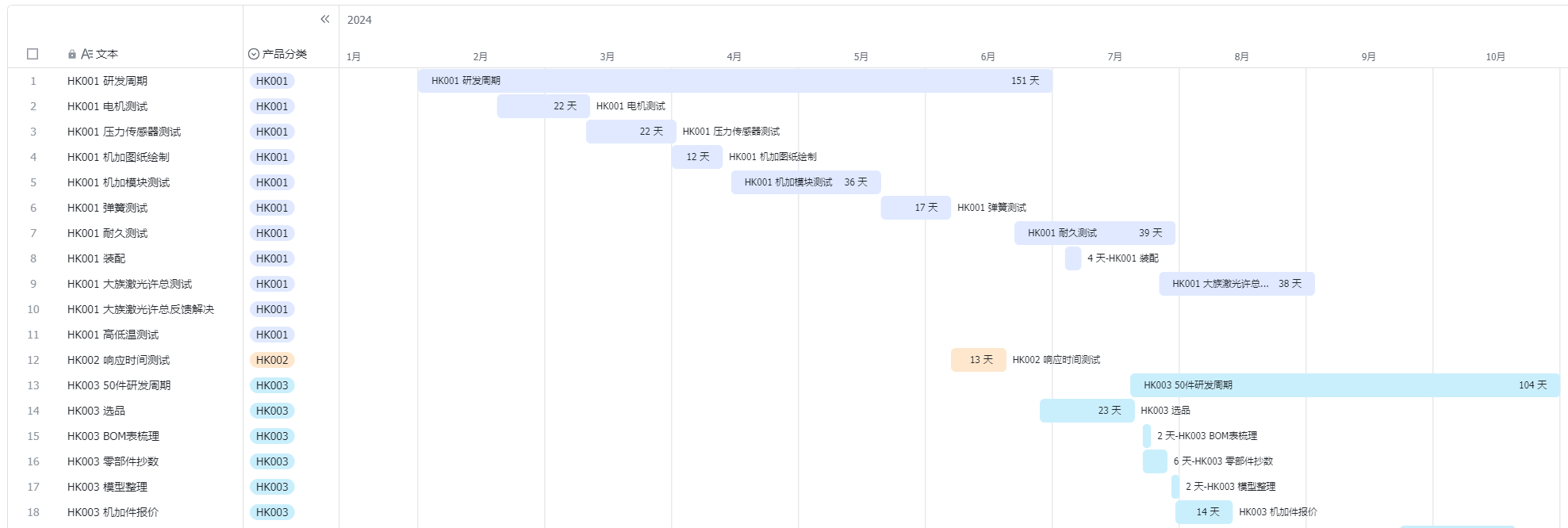
This schedule chart reflects hands-on project coordination across testing, drawing release, endurance validation, and assembly, with each task tracked over the 2024 development cycle.
Supply Chain Management
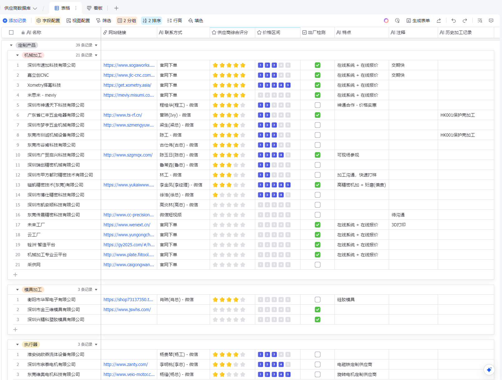
This supplier database reflects practical supply-chain work, organizing machining, mold, and actuator vendors with contacts, ratings, pricing, and inspection status for sourcing decisions.
Multi-functional Teams Collaboration
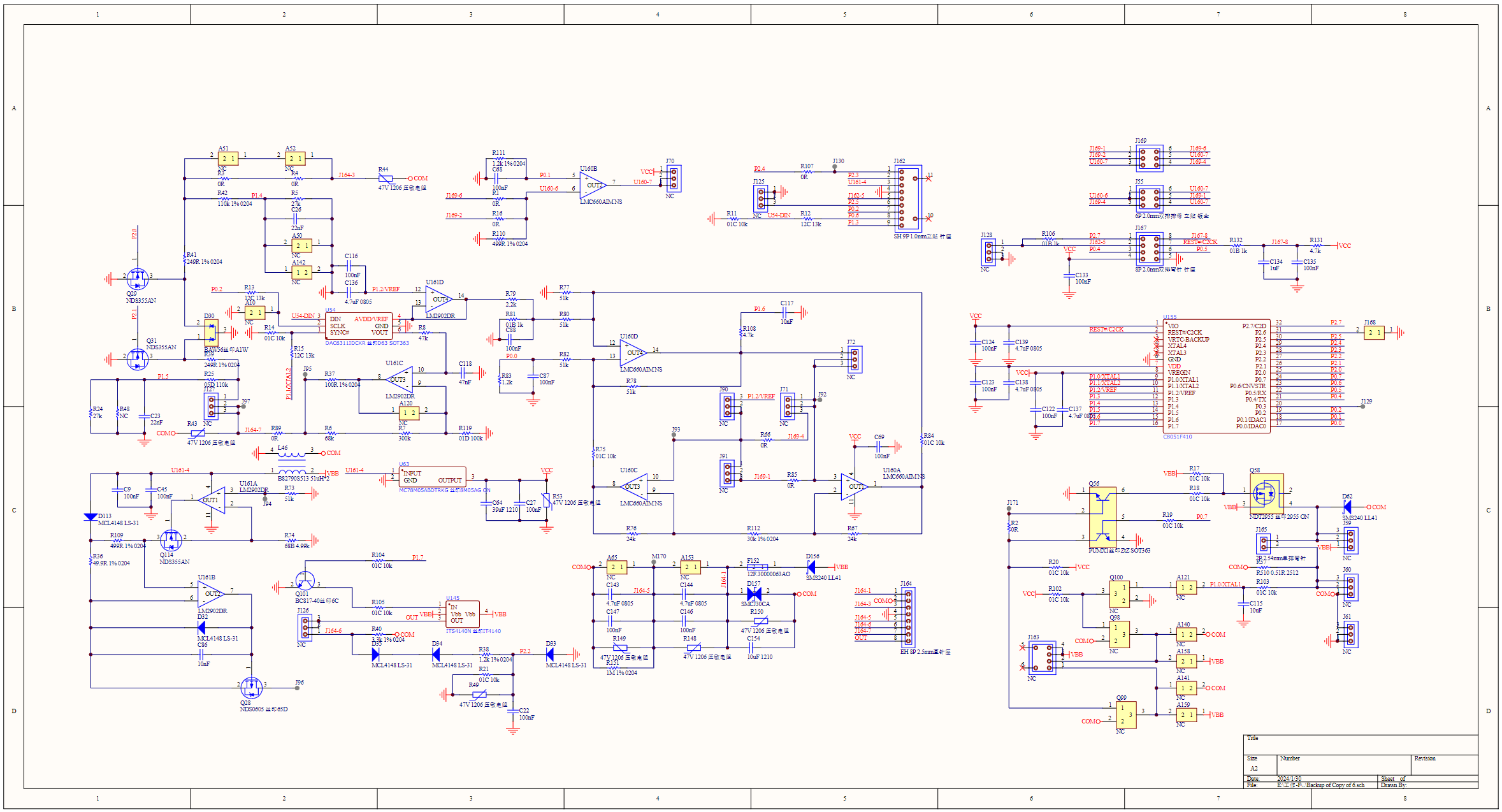
This schematic sheet shows involvement beyond mechanics, covering the control-side circuit with chips, resistors, capacitors, transistors, and signal interconnections.
Production Requirements
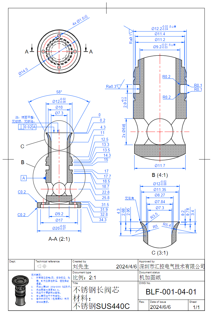
This manufacturing drawing demonstrates detail-oriented engineering output, defining the valve core through views, sections, dimensions, and material notes for production.
Combined Tolerance Inspection
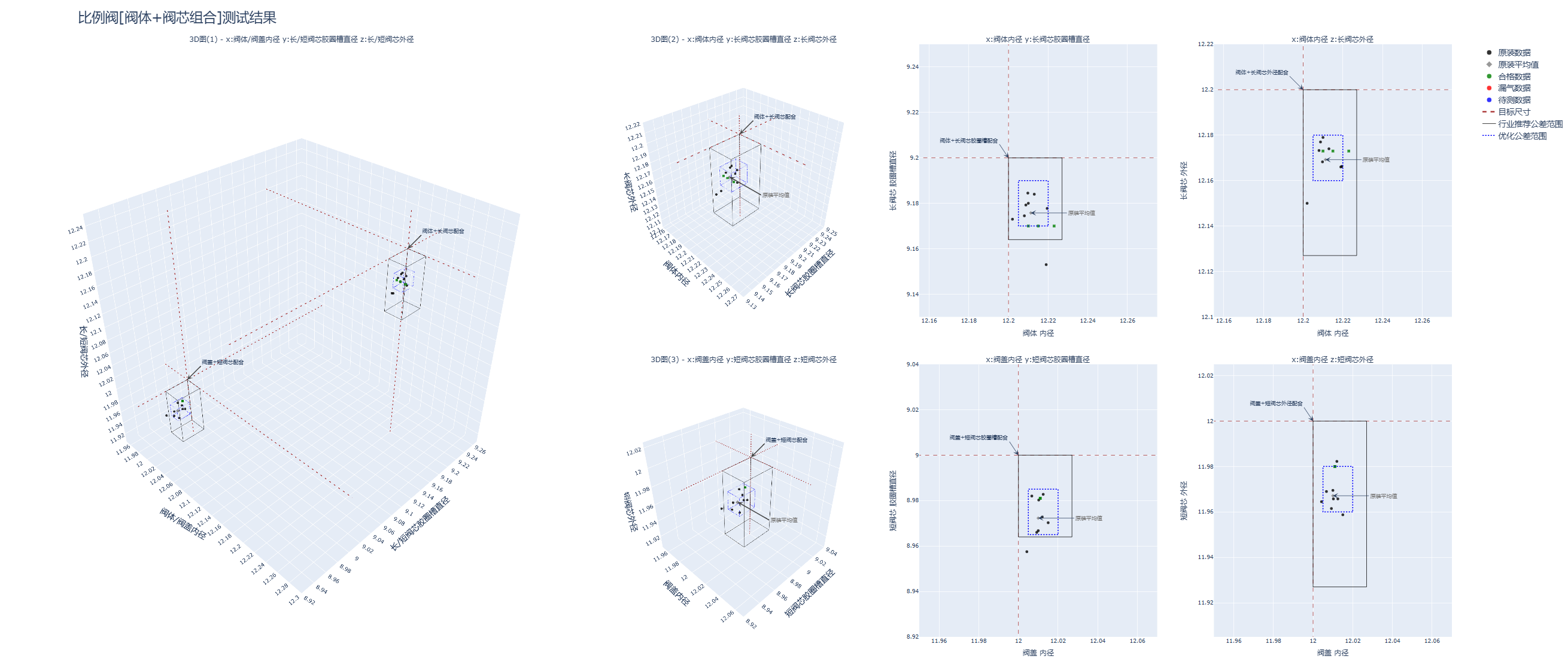
This tolerance analysis highlights inspection and quality-control work, using 3D and 2D scatter plots to compare measured valve-body and valve-core dimensions against limits.
Spring Force Testing
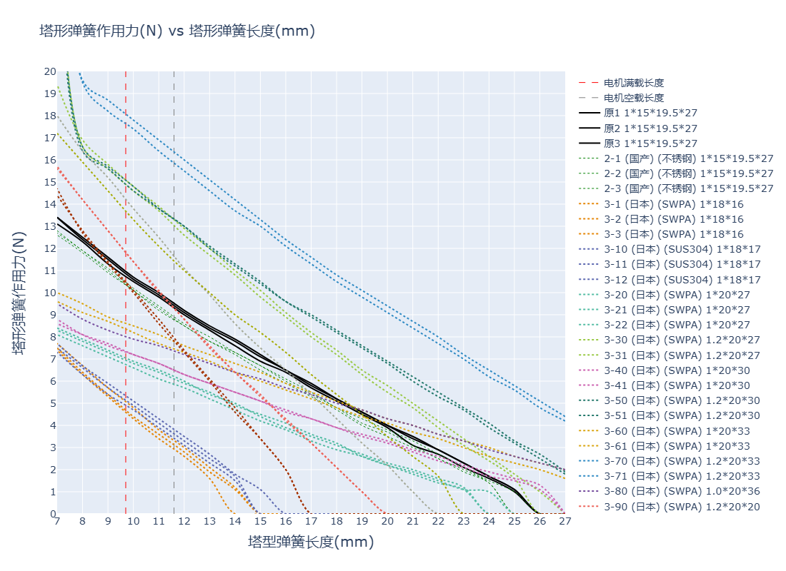
This spring characteristic plot reflects test-driven design work, comparing force-length behavior across multiple spring materials or design variants.